

Introduction: DC Ground Fault Locating
Compliance with NERC PRC005-6 requires that the battery and DC power system be inspected for inadvertent grounds every four months. If a ground fault exists the DC Scout is the tool by which that fault can be located without the need to de-energize the live circuit.
When you’re under tight time constraints, quickly locate faults with the DC Scout—with as little as 2 mA of current. The D.C. Scout is used for locating resistive or non-resistive current paths from DC Battery Distribution System to building ground without de-energizing components or loads in the system.
Works on the following battery voltages: 24 VDC, 48 VDC, 125 VDC, 250 VDC
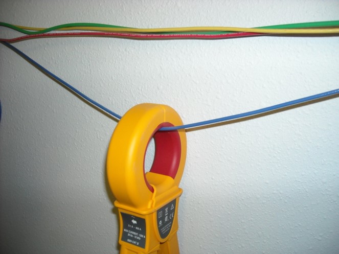
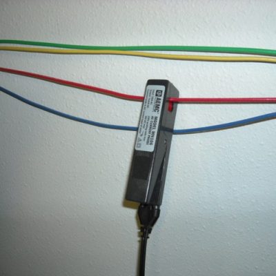
By placing the detector CT probes on different sections of the wire, the user is able to trace the pulse. When no pulse is detected, there is a fault in the wire. The pulse has been grounded.
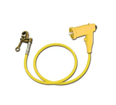
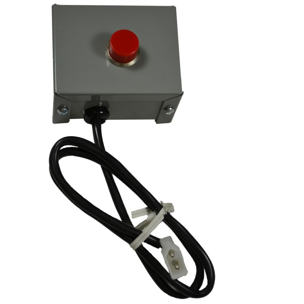
The D.C. Scout package has an External Pulse Indicator Lamp. This lamp is handy for seeing when each pulse from the Pulser Unit occurs, even when the user may be 40 yards or more away from the Pulser Unit.
Downloads:
- DC Scout BROCHURE 2026 (PDF)
- DC Scout Operations Manual (PDF)
- DC Scout Tutorial (PowerPoint)
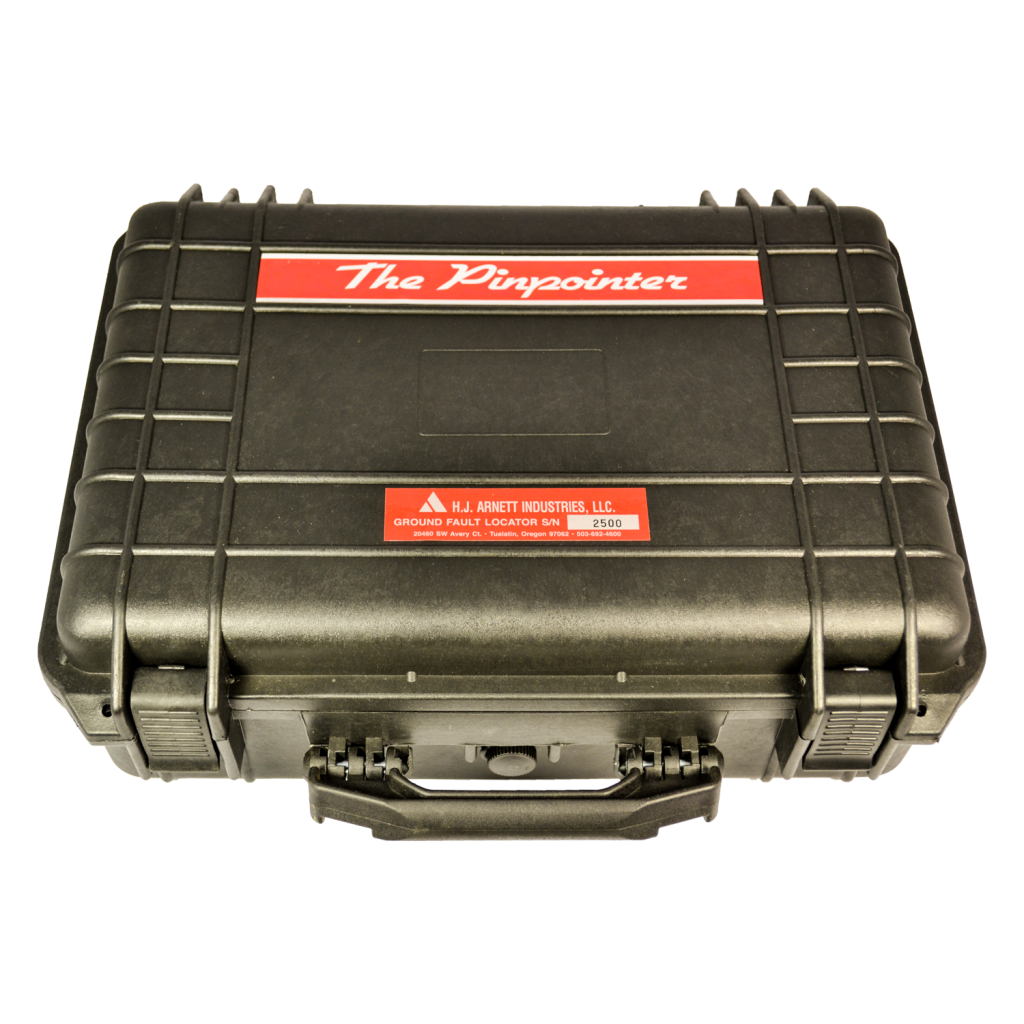
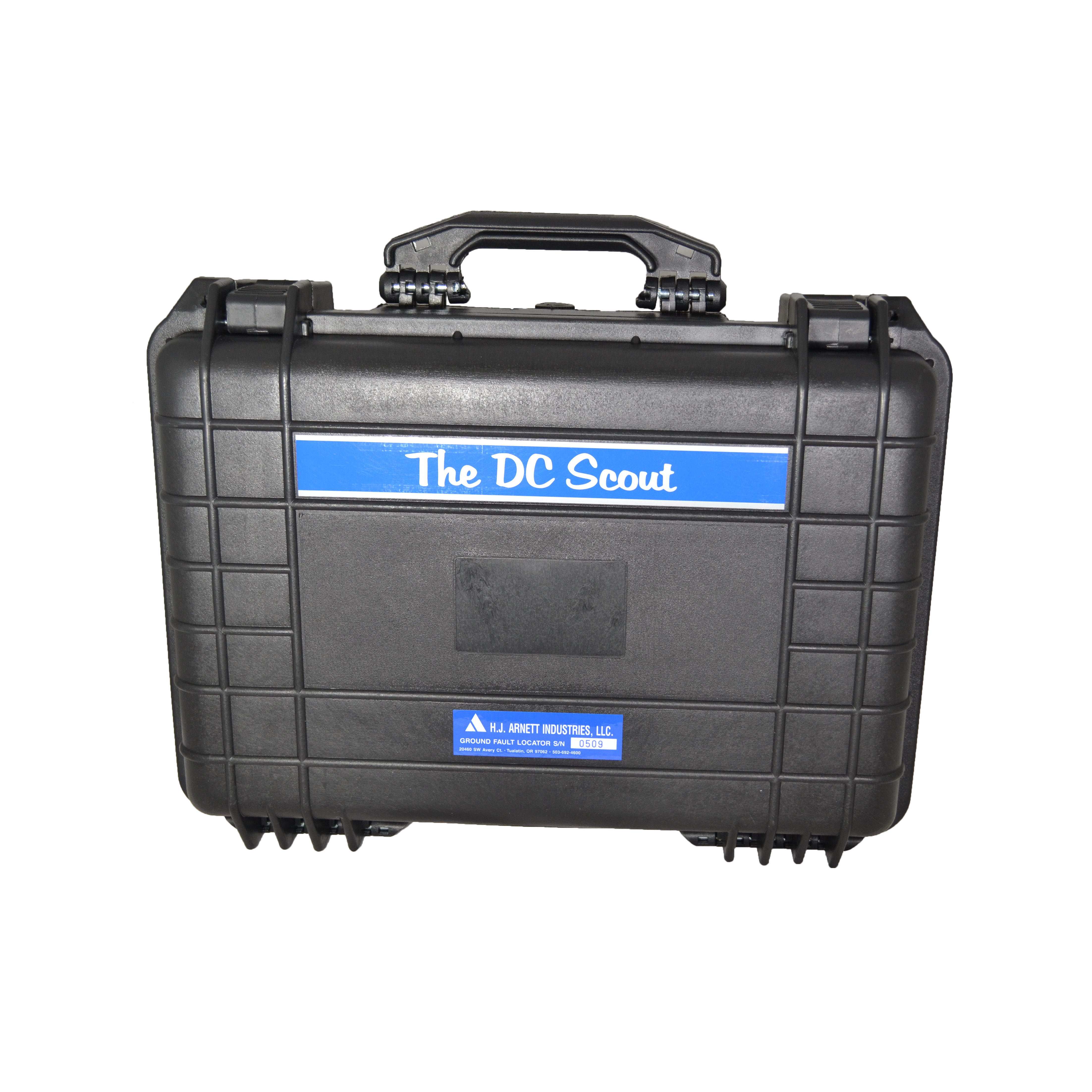
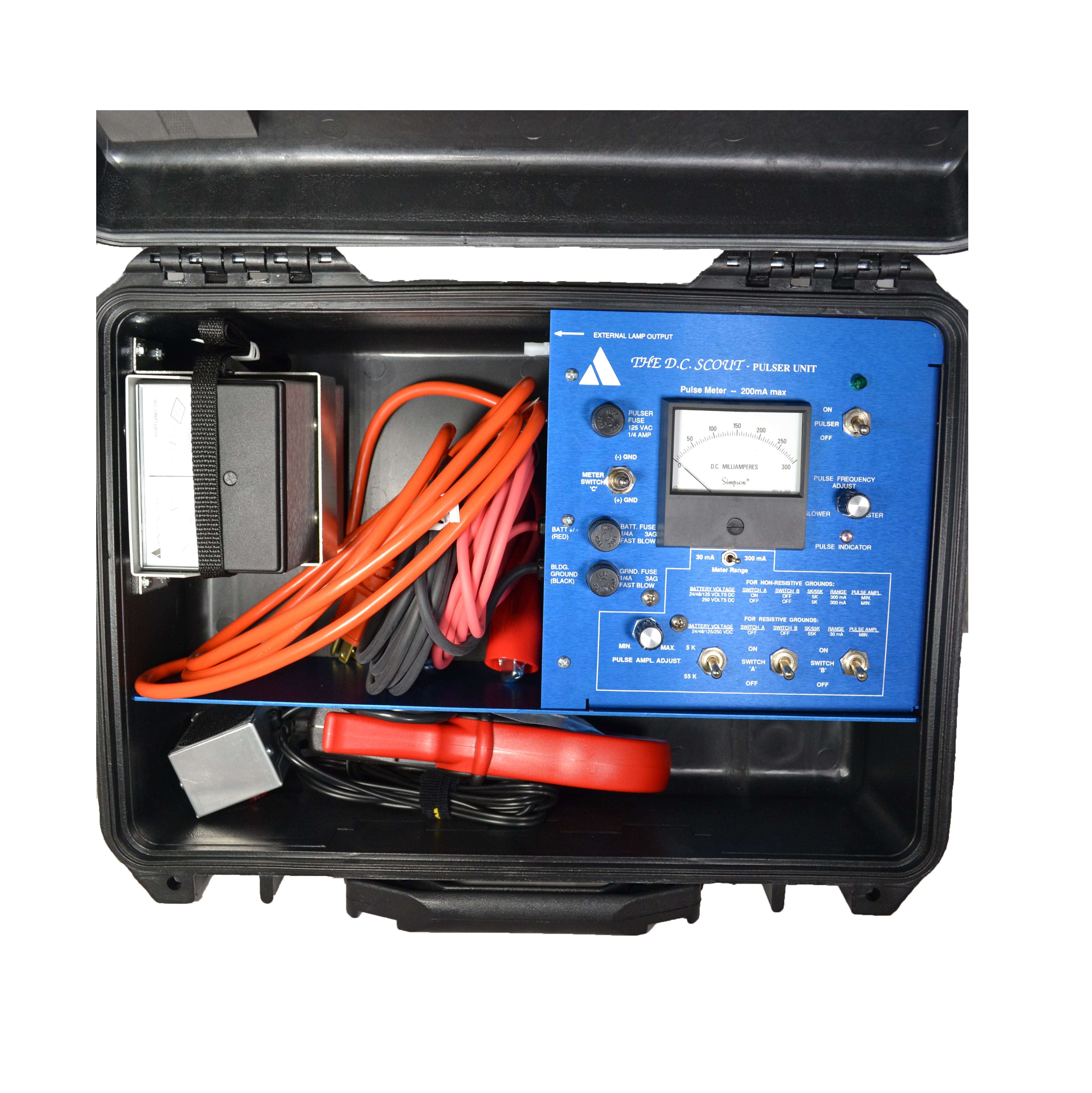
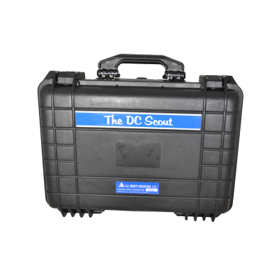
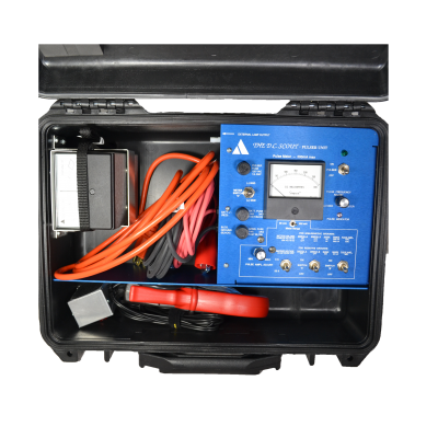
The DC Scout Includes:
Transmitter (pulser unit), Detector, 2″ CT probe, Lamp (blinks with transmitter pulse), Toolbox instrument case
Toolbox case dimensions: 21″ x 11″ x 10″
DC Scout shipping weight: 21 pounds
Benefits:
- No disconnecting leads to isolate grounds in complex DC circuits
- Follow pulses to ground with clamp-on detector probe
- Troubleshoot critical control systems quickly and accurately
- Locate grounds with as little as 2 mA of current
Our DC Scout Customers Include:
- American Electric Power (AEP)
- Alabama Power
- Mississippi Power / Southernco
- Dearborn Industrial Generation
- Delmarva Power
- Detroit Energy (DTE Energy)
- Dominion Energy
- Duke Energy
- First Energy
- Georgia Power
- Gulf Power
- Jackson Energy Authority
- Mississippi Power
- Portland General Electric
- PG&E – California
- PSEG – New Jersey
- Public Service Colorado
- Santee Cooper
- Southern Power / Southern Companies
- Tennessee Valley Authority
- XCEL Energy
- More references available upon request. Please email [email protected] for more references.
Customer Testimonials:
“We had great success with the DC Scout test set. We were able to locate the ground on an energized 125VDC system. It ended up being a ground fault located in a one-inch underground metal conduit. The ground was on a 12 AWG wire feeding to an 86 circuit. The test signal was found on the wire going into the conduit and was gone when the wire left the conduit. This indicated the fault was located in the pipe.
We safely isolated the faulted cable, tested it, and found it bad then utilized a spare in its place. No interruptions were initiated by the test set signal even with solid state relays on the circuit and we found our first fault in less than two hours. The set is well worth it and easy to learn.”
- -Power Solutions Associates
How the DC Scout Fault Locator Works:
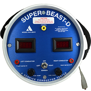
Instrument consists of two basic parts:
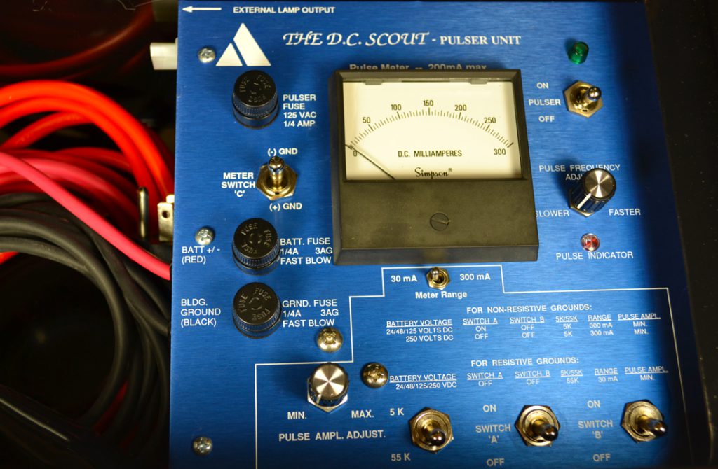
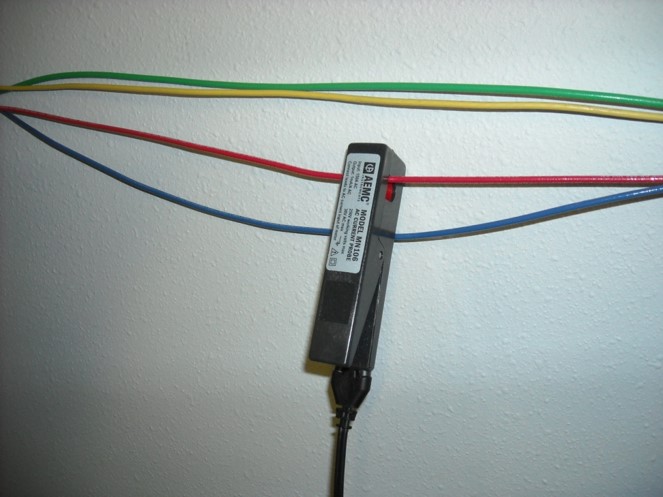
- Pulser Unit: Used to pulsate current through the DC battery – DC Scout – building ground loop
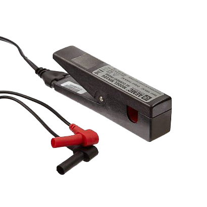
- Pulse Detector Unit: Used to detect pulses generated by the Pulser Unit in the DC battery – DC Scout – building ground loop


The D.C. Scout repeatedly opens and closes (pulses) the closed circuit, established when D.C. Scout is connected. Current flows from the (+) battery pole, through the wire shorted to building ground, through the D.C. Scout building ground lead, then back through the D.C. Scout +/- battery lead to the negative battery post.

- Note that the ground detection system battery is the source of the current flow, not the Scout.
- The D.C. Scout’s pulser unit continuously generates pulses, and the detector meter shows the pulse when the current transformer(CT) probes are connected to the line.
- The fault is tracked by moving the CT’s to different locations on the line, moving towards the direction that causes the pulse amplitude to shrink. The fault is found when the pulse amplitude is zero. This systematic approach of noting where pulses have been detected, then moving down the wire to where pulses are not detected, pinpoints the ground fault location.
Precautions:
- Always wear proper Personal Protection Equipment when working on and around energized circuits
- Work involves energized circuits
- Inspect all energized equipment for proper installation and functions before initializing work
DC Scout Limitations:
- D.C. Scout Pulser Unit should be connected in parallel with grounded circuit (positive or negative ground); it will have full battery voltage across it for a solid ground or partial voltage across it for a resistive ground.
- Pulse amplitude will be set for a minimum of 5 mA to a maximum of 200 mA DC.
- D.C. Scout Pulser Unit has two in-line fuses to ensure protection of D.C. Scout and system it is analyzing. If more sensitive protection is desired, a lower amperage quick-blow fuse may be substituted; this would limit output capacity of D.C. Scout.
- Under no circumstances should a fuse rating of more than 250 mA be installed in BATT FUSE or GRND FUSE fuseholders.
- With both Switches A and B on, there is no current limiting resistors in circuit and it is possible to quickly blow D.C. Scout Pulser Units BATT FUSE or GRND FUSE.
Usage Tips:
- At times there can be difficulty discerning between the desired pulses on the Detector Meter and random pulses, or “noise.”
- For those pulses/spikes, which are circulating from (-) to (+) in the circuit, clamp the D.C. Scout’s Pulse Detector Probe around both (-) and (+) wires at the same time. The circulating pulses will cancel out and you should see only the D.C. Scout’s pulse, which is not circulating on both the (+) and (-) wires.
- For those pulses/spikes that are radiating down a wire and are not circulating, move down the wire, if possible, to get away from noisy systems such as choppers, and inverters. It may be necessary to decreases the sensitivity of the Pulse Detector and increase the amplitude of the D.C. Scout’s pulse in order to override the remaining interference.
- The “Pulse Frequency Adjust” control on the D.C. Scout Pulser Unit can be adjusted so that the frequency of the Scout’s pulses stand out from the existing noise.
DC SCOUT SPECIFICATIONS:
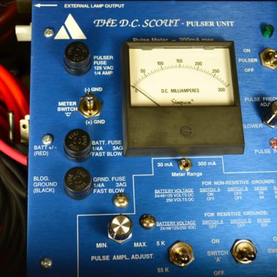
Pulser Unit (Transmitter):
- Description: Housed inside instrument case, mounts pulse meter and user adjustable controls
- Operating Voltage: 125 VAC, 250 mA front panel fuse protected
- Relay Output: 250 VDC, 250 mA front panel fuse protected
- Relay Timing: 2 to 8 cycles per second, user adjustable
- Relay Indicator Lamp: 14 VDC, bayonet style
- Pulse Amplitude Meter: 0-300 mA DC, pivot and jewel style, with user selectable 30 or 300 mA range
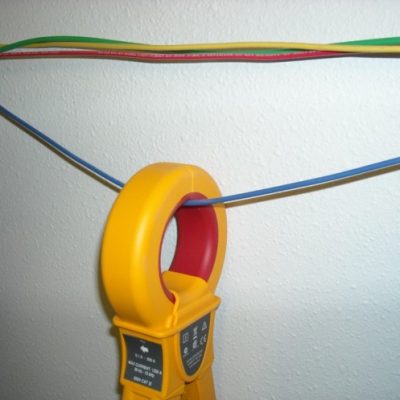
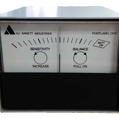
Pulse Detector:
- Description: Super-sensitive pulse amplifier, housed in poly carbonate shell with neck strap
- Operating Voltage: 9 VDC, transistor battery powered
- Meter: Taut band, zero-center
- Detector/Probe Sensitivity: 2 mA min. pulse amplitude (for detectable meter movement; slightly more for optional probe)
- Sensitivity/Balance Controls: Adjustment controls mounted on rear panel
- Battery Test: Rear panel push button with meter indication
- Dimensions & Weight: 3 3/8″ x 3″ x 5 1/8 ” – 1lb
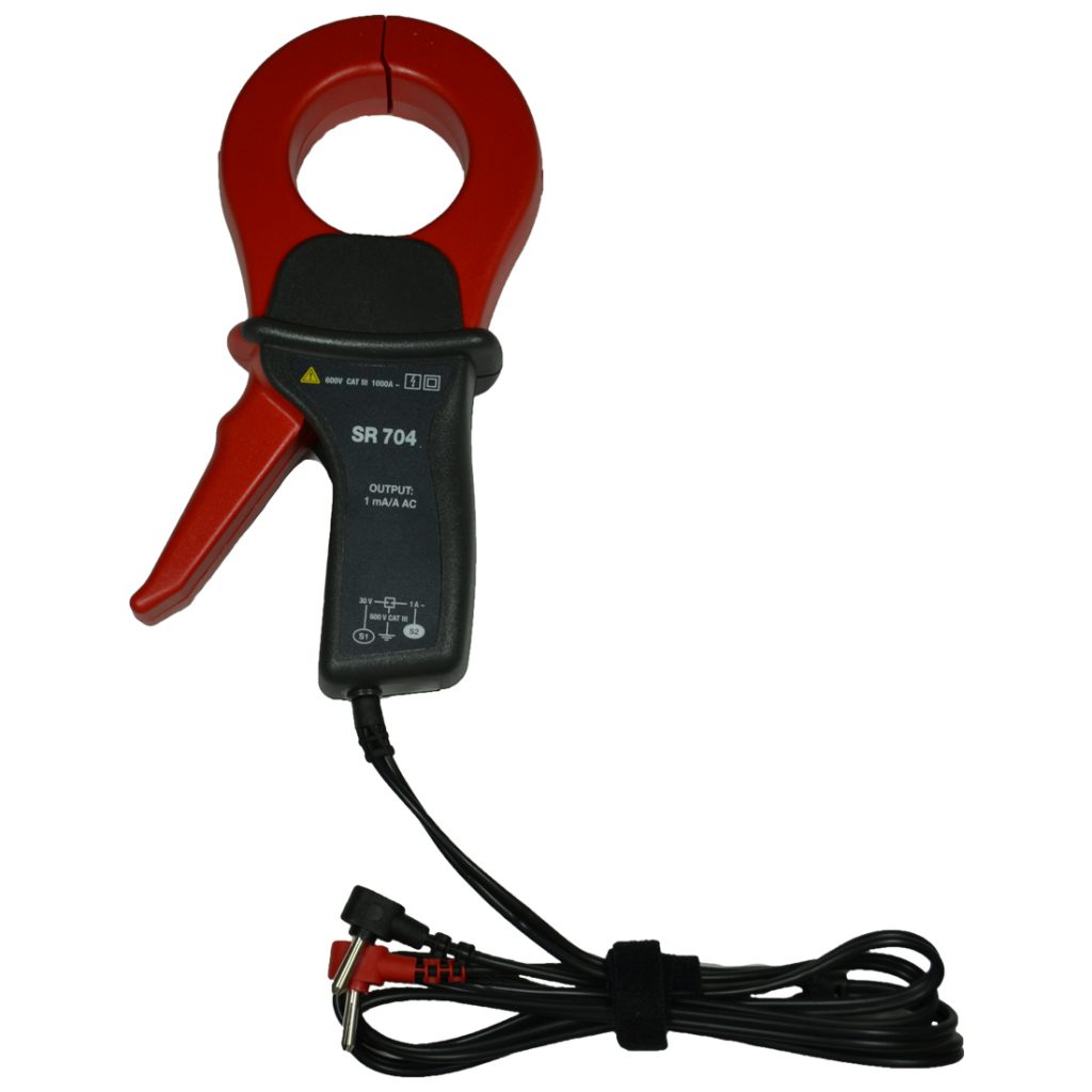
Current Transformer Detector Probe Options:
- Standard Probe: 2″ circular jaws, 14oz.
- Optional Probe: .5″ x 4″ opening, 5 oz.
DC Scout Configurations:
- The D.C. Scout can also be configured for 220 VAC (P/N: HJA-2525-220)
Locating A.C. Grounds
- The D.C. Scout can be used to locate grounds on A.C. system up to 480 volts, provided the following conditions are met.
- The A.C. circuit must be totally de-energized and disconnected from its source. This means all phase leads and the neutral lead, if used.
- A 130 Volt D.C power supply must be available that is capable of supplying 200 mA of current. This D.C. voltage must be isolated from ground. This means that the (+) and (-) leads each read zero (0) volts to ground when energized.
Applications:
- Nuclear plants
- Power generation plants
- Oil refineries
- Chemical plants
- Ships
- and fire alarm systems
WARNING: Cancer and Reproductive Harm – www.P65Warnings.ca.gov